Hi!I am encountering a problem with AD9739.my system board with AD9739 is used to produce some waveforms,when ad9739 is clocked in 1G ,the board can get good signal(the output signal freq located in the second Nyquist zone);while clocked in other frequency just like 1.4G,the ad9739 can not work well,output with periodical spurious,the period is about 30 microseconds.I have another board almost the same ,but can work properly.I don't know how,so can you help me?
↧
AD9739 output with periodical spurious
↧
ADV 7403
Hi I am currently working with ADV 7403 how can it be used to add subtitles into a PAL based video
↧
↧
S Parameter Information
Hi,
Kindly provide S Parameter file for HMC951B.
Regards
San
↧
For the AD9364, what is the minimum operational SPI data rate?
Hello,
I would like to know if theres any minimum operational SPI_CLK rate allowed. I could easely find the maximum SPI_CLK in the documentations (datasheet and reference manual), but I was unable to find any data related to the minimum clock rate possible that keeps SPI communications operational.
Best Regards,
Túlio Pedrosa.
↧
ADV7611 DDC and RXA_5V fault tolerance
Hi,
In ADV7611 EVM, DDC signals and 5V HDMI signals are being driven when the board is powered OFF and HDMI cable is connected. Is this fine w.r.t. ADV7611 pins, even when there is no supply to ADV7611?
Regards
Raja
↧
↧
Please help about tools/method to calculate the all the Register Value for different output frequency
Hi, gentlemen
do you have a tools to calculate the all the Register Value for different output frequency? Initially we use the external IO set output frequency, while not flexible
if we would like to set AD9552 output frequency to increases progressively (e.x 161.132813MHz then next 161.132814MHz, then 161.132815MHz), how to quick get the DXCO / OPPLL /SDM regsiter value setting, maybe a tools or method, Could you help on this?
we could access all the register(read and write works). just to want to know how quickly get the reg value.
if we can't get the frequency output increase 1Hz by 1Hz, the following frequency is we need, could you help on PFD/PLL/SDM relate reg value.
| 161.1328125MHz |
| 168.040678MHz |
| 167.3316456MHz |
| 161.1328125MHz |
| 168.040678MHz |
| 167.3316456MHz |
| 173.4375MHz |
| 174.099823MHz |
| 176.0951451MHz |
| 176.8381626MHz |
| 179.1343MHz |
| 179.6875MHz |
| 187.5MHz |
Jizhong
Hz'z
↧
What is the expected quiescent current on the VNEG pin of the HMC980?
I'm using 1 HMC980 to generate the -2.5 volts for itself and 3 other HMC980s. It seems that the voltage generated is being dragged down to about -2.1 volts. Is it possible that the total quiescent current of the four chips is too much?
Will this be an issue for proper HMC980 operation? How much current should I expect them to draw.?
↧
Fast Lock with frequency change of more than 100MHz
When creating the Fast Lock profile registers for Rx and Tx and storing it in the BBP , is it also good for a defined desired frequency with change more than 100MHz ?
On table1 of UG-570, it says that a RF DC offset calibration as well as RX and Tx quadrature calibration needed for frequency changes more than 100MHz.
If the answer is Yes than what are the other Registers needed for Fast Lock profiles.
↧
ADAU1401 iis 输入 无输出求解决
请教下ADAU1401IIS输入时,原理图怎么选input pin 我按照datasheet 设置好后DAC没有输出,求大神指教
↧
↧
AD7763 On board Diff Amp
Hello,
Can you confirm if the onboard diff amp is good enough to drive the AD7763, or does it require and external diff amp?
↧
[ADXL354-ADXL355] Frequency response for seismic purposes
Hi to all, I don't know if someone would be already interested about using these MEMS accelerometers for seismic purposes (or has already done this).....
I have some doubts about frequency response.
page 3 of datasheet:
resonant frequency (1) = 2.4 kHz
(1) sensor characteristic [...] an analog 1.5kHz (-6dB) that cannot be bypassed limits actual output response
page 23 of datasheet:
The ADXL354/ADXL355 use an analog, low-pass, antialiasing filter to reduce noise and limit banwidth.
The ADXL355 provides further digital filtering options [...]
The analog, low-pass antialiasing filter [...] provides 1,5kHz bandwidth where output response is attenuated by 50%. The shape of filter response in the frequency domain is sinc3 filter.
So I understand both have got same internal low-pass filter, but in graphs shown in fig. 7, 8, 9 for ADXL354 shows 2400 Hz peak (I suppose resonance frequency), so without low-pass analog filter.....?????
1) I need poles and zeros to simulate frequency response of filter (usually seismic sensors have given poles and zeros from which take out bode diagram for further analysis for compensation in terms of magnitude and phase). Is there a way to know parameters (poles and zeros) to do sensor simulation?
Talking about ADXL355:
Additional digital filtering [...] consist of low-pass digital decimation filter.
[...]
The first stage is fixed decimation filter with a 4kHz ODR with a low-pass filter cutoff (50% reduction in output response) at about 1kHz.[...] second stage decimation filter is used for 2kHz output data rate and below [...]
Figure 60 shows the low-pass filter response with 1kHz corner (4kHz ODR) for ADXL355.
So first stage is decimation (low-pass) filter with sampling frequency of 4kSPS, I suppose the one in fig. 60 (not taking care of analog filter, right?), so why sampling frequency of fig. 60 looks like 20 kSPS?
I'm a bit confused.....
2) are there available digital filter (stage 1 and 2) coefficients or instructions to replicate model in Matlab?
Thanks.
↧
ADF4158 operation via SPI
Hi
I am using ADF4158 PLL, and wants to generate triangular FMCW signal with a frequency of 1.5GHZ and 30msec time duration. I configured certain register values for getting the above requirement. Unfortunately I don't have oscilloscope with GHz range so physically I can't my signal pattern. The following are the register values for SPI communication
- define Reg0 (uint32_t)0x80190D48
- define Reg1 (uint32_t)0x0FBE0001
- define Reg2 (uint32_t)0x03008DB2
- define Reg3 (uint32_t)0x00000443
- define Reg4 (uint32_t)0x00180084
- define Reg51 (uint32_t)0x20019E45 Register5
- define Reg52 (uint32_t)0x20819E45 Register5
- define Reg61 (uint32_t)0x00001FFE Register6
- define Reg62 (uint32_t)0x00801FFE Register6Please give me some relevant examples for my understanding.Thanks
↧
can ADAU1701 SDATA inputs be pulled low?
Hi,
I am working on an application where the ADAU1701 is receiving serial audio data on Multifunction Pin 1 that has been configured as serial audio data input.
It seems that this pin is always pulled up. The same stands for all other multifunction pins when set as SDATA inputs.
I was wondering if those can be pulled low.
On another application using an ADAU1761 I can choose to pull-up/down the SDATA lines. But it does not seem possible with an ADAU1701. Is that correct or I just need to write the right register in order to do that?
cheers,
Dimitris
↧
↧
AD5934(EVAL-CN0349) output frequency problem
Dear All,
I have some problem with the output frequency on my EVAL-CN0349 board. I found out this problem in connection of my other issue(Measure conductivity below 25us with EVAL-CN0349 (AD5934) ).
So I measured the output frequency on my eval board and it seems that it cannot genarate the proper output frequency. The voltage is proper. So I started to debug my code to see if I made any mistakes. I found one and corrected it, now I can set the system clock bit in the control register just fine. The start frequency code is calculated and written into the device properly. I checked it.
I want to set 30kHz but I only get around 6kHz in case of internal clock(today I will try to measure the output frequency at more setpoints and I will refresh this post), the frequency increment works but also not properly. The device increments the frequency but not with the given value it seems.
I started to read some discussions on the forums and I found the next:
AD5933: Initialize With Start Frequency Command Not Working
in which snorlax states the following:
Also make sure that the chip is not the AD5934 - the version that does not have the internal oscillator.
Now these confused me. Can somebody help me to clarify this?
Is there internal 16MHz clock in the AD5934? (According to its datasheet yes, and my setup works with the internal clock setting just the frequency is not proper)
As the documentation of the circuit states(http://www.analog.com/media/en/reference-design-documentation/reference-designs/CN0349.pdf ) :
The frequency of the clock applied to the MCLK pin is set to
1 MHz using a stable, low jitter, FXO-HC536R-1 (U6) quartz
crystal oscillator. This oscillator allows the AD5934 to excite the
conductivity cell with a frequency of 2 kHz, which is well suited
for conductivity measurements.
Naturally I tried the measurements with the output clock but the output frequency is not good in this case either.
What else could I do to correct the output frrequency, or what should I check? I have checked the following things:
-clock setting in the control register OK
-start frequency code OK
-increment frequency code OK
-start frequency and increment frequency code write to the registers OK
Thanks for the help!
↧
What is the HMC703 SPI minimum interval?
hi,
I use the HMC 703 through SPI of 50MHz clock speed.
When I changing the sweep mode, I have to change several register values.
After writing a single register value, how much time I need to wait for rewrite?
When I tested, the interval delay required 400ns.
It takes 640ns to transmit 32bit data, so I think the interval delay of 400ns is too long.
I need your help.
Think you.
↧
HMC832 DVDD series resistor
Why does the HMC832 Evaluation/Reference design (HMC832LP6GE) have a 50 Ohm resistor (R19) in series with the DVDD supply?
↧
Looking for High-Speed ADC FMC Card for Zedboard
Hello,
I'm looking for a High-Speed ADC FMC Card for the Zedboard.
I found this: AD9467 Native FMC Card / Xilinx Reference Design [Analog Devices Wiki]
But I can not be sure if it fits my requirements. I'm hoping you can help me out.
I am trying digitize the video output of the analog camera: Sony CX-HR50. The datasheet can be found here Sony Product Detail Page XCHR50 . It's a progressive scan black and white CCD Camera.
The Video Ouput looks like this on an Oscilloscope:
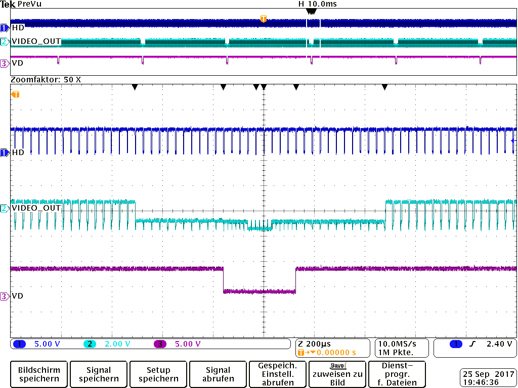

Do you think the AD9467 FMC Card is an appropriate ADC for the Camera? Or can you suggest another FMC Card fr my purpose?
Thank you!
↧
↧
Detecting overload or saturation condition in AD9361
I'm using the AD9361 along with the No-OS driver. I would like to be able to detect when an RF signal is saturating/overloading the AD9361 such that the user must change the gain (manual mode) or remove the signal (fast/slow AGC). If in slow/fast-AGC mode the AGC can no longer compensate, at which point I alert the user that output may be unusable. If in manual gain mode, I can alert the user to decrease gain or switch to AGC.
Looking at ad9361_api.h, I don't see anything readily available to check for overload or saturation. I think I would have to create a function that reads the Large ADC overload bit and if it is set for a period longer than the AGC would take to compensate, then we can flag an overload condition to the user.
Would you suggest using that method for detecting a saturation/overload condition? Or are there other registers/bits I should monitor? Should I monitor the LMT in addition to ADC saturation?
↧
Creating a Custom ADC Board for ADS7-V2EBZ
Hi there
I am interested in creating a custom version of the AD9695-1300EBZ board to test with the ADS7-V2EBZ. The only issue I foresee occuring the EEPROM - how necessary is that when creating a daughter card for the ADS7-V2EBZ? I presume it has some settings for interacting with the motherboard.
If it is necessary, would it be possible to obtain that firmware or binary blob and program our own EEPROM?
Thanks,
Brady Salz
↧
QPSK and QAM examples not working properly
I have a ZedBoard and an ADI FMCOMMS 3, and I’m trying to follow the examples mentioned in the “AD-FMCOMMS2/3/4 Datafiles” document:
I have worked on both QPSK and 16-QAM examples. However, I’m not getting any correct results when viewing the constellations using the ADI IIO Oscilloscope. For the QPSK, the results look more like a very noisy 16-QAM constellation as seen in the next screenshot:

I tried changing the parameters of the FMCOMMS using ADI IIO Oscilloscope to make the output clearer, but without any success. However, when I use the data file mentioned in the documentation (qpskwithfilt_txt.zip), I get a clean result:

If I’m not mistaken, this indicates that there aren’t any configuration errors in my FMCOMMS3 board. I would also like to note that the output data from the simulation “qpskwithfilt.slx” is completely different from the data in “qpskwithfilt_txt.zip”
I then tried the 16-QAM example to see if it will work. The constellation isn’t clear at all, and the output looks more like a noise than a signal as seen in the next screenshot:

The only difference in settings I made for the QAM is changing the sampling rate to 20 MHz. The output data from the simulation has some differences to the file uploaded in the documentation (qam16_20mdata.zip).
My question is, what is the cause of this behavior? Take into consideration that one of the data files uploaded in the documentation works without any problem.
↧